Summary
Main power cables are the primary path that delivers electrical energy to a passenger coach’s systems, including air conditioning, lighting, and controls. When a coach has been through an event that may damage its wiring, such as an accident, replacing the cables to sound engineering practice and verifying insulation resistance beforehand are key steps in returning it to safe service. This article explains the underlying principles and presents a case study from WCE’s Rail Technology and Engineering Business Unit (RTE).
1. What Are Main Power Cables in Passenger Rolling Stock?
Passenger coaches need electricity for onboard systems such as air conditioning, lighting, and control equipment. In many systems, power is supplied from a main source in the train and distributed along its full length through main cables routed inside each coach and connected between coaches by jumpers and receptacles. For example, the American Public Transportation Association (APTA) recommended practice for 480 Vac Head End Power systems specifies multiple jumpers connected in parallel at each car-to-car connection and systematically addresses cabling, power distribution, and testing [3].
Because these cables carry power for several coaches in sequence, a single point of damage can affect power supply to the whole train.
2. Key Principles
2.1 Railway Cables Are Purpose-Built
Cables used in railway vehicles must withstand conditions different from those in buildings, including vibration, temperature, and fire-safety requirements. The European standard EN 50264 covers power and control cables with special fire performance for railway rolling stock and sets requirements for insulating and sheathing materials [2]. Its part on single-core cables, for example, specifies halogen-free crosslinked elastomeric insulation with a continuous conductor temperature of 90 °C [5].
2.2 Installation and Cable Support
Quality depends on how cables are installed, not only on the cables themselves. EN 50343 specifies requirements for installing cabling on railway vehicles, covering cables, busbars, terminals, and plug-and-socket devices [1]. APTA recommends insulated cable cleats at intervals of no more than about 1.22 m (4 ft) to support power cables [3]. Good cable support reduces chafing and vibration damage in service.
2.3 Insulation Resistance Testing
An insulation resistance test applies a DC voltage to the conductor and measures the small leakage current through and across the insulation, reporting the result as resistance in megohms. It is a non-destructive method [4]. Common approaches include:
– Spot reading – voltage is applied for a set time, typically 60 seconds, and the value is read [4].
– Time-resistance and Polarization Index—readings taken at different times are compared; good insulation shows a continual increase in resistance over time [4].
The same source gives a rule of thumb of roughly one megohm per 1,000 volts of operating voltage and notes that test voltage should be chosen according to the equipment’s rating [4]. Actual acceptance criteria for any project depend on the applicable standards and the system owner’s requirements.
APTA’s recommended practice also includes continuity, insulation resistance, and dielectric tests as part of HEP system testing [3].
2.4 Why Cabling Matters in Post-Accident Repairs
Insulation can deteriorate from mechanical damage, vibration, heat or cold, moisture, and contamination. Cracks or pinholes invisible to the eye can become leakage paths [4]. In an accident-damaged coach, cables may have been impacted, crushed, or exposed to heat. Installing a new cable set and verifying insulation resistance helps confirm the system’s condition before the coach returns to service.
3. Case Study: Main Power Cable Replacement on an Accident-Damaged Passenger Coach by WCE’s Rail Technology and Engineering Business Unit (RTE)
– Scope: Electrical works—complete replacement of 8 main power cables, covering both inter-car and in-car cabling; insulation resistance testing with a full test report; and handover of the coach for subsequent installation work carried out by others
– Client: A client in the rail sector
– Progress: 100% completed
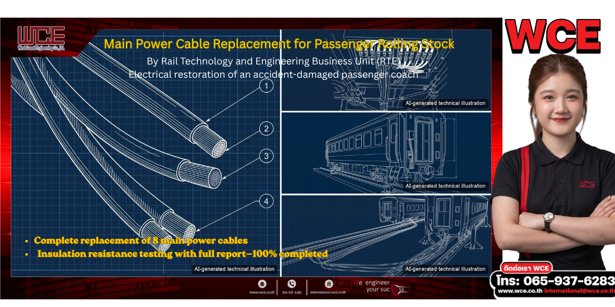
The cover image shows the key elements of the work. The large image on the left shows the main power cable ends stripped and prepared for termination. On the right, from top to bottom: an underframe terminal box, a passenger coach raised on lifting jacks during repair, and inter-car cable routing. All images are AI-generated technical illustrations, not photographs from the actual site, and do not identify any individual, client, or vehicle.
4. Observations from This Project
– Post-accident coach repairs are often split into several work packages. Clearly defining the electrical scope and handing over in the right sequence keeps the other work packages on schedule.
– Insulation resistance testing with a documented report provides technical evidence that helps the system owner return the coach to service with confidence.
– Replacing the complete cable set reduces the risk of hidden damage in the original cables.
5. WCE Services
WCE’s Rail Technology and Engineering Business Unit (RTE) provides engineering and maintenance services for railway rolling stock, including coach electrical systems—from cable replacement and installation to testing and reporting.
Contact: +66 65-937-6283 | international@wce.co.th | www.wce.co.th
We engineer your success.
References
[1] CENELEC. EN 50343:2024 Railway applications – Rolling stock – Rules for installation of cabling. https://evs.ee/en/evs-en-50343-2024 (accessed 8 Oct 2026)
[2] CENELEC. EN 50264-1:2008 Railway applications – Railway rolling stock power and control cables having special fire performance – Part 1: General requirements. https://www.evs.ee/en/evs-en-50264-1-2008 (accessed 8 Oct 2026)
[3] American Public Transportation Association (APTA). APTA PR-E-RP-016-99, Rev. 2: 480 Vac Head End Power System. 2026. https://www.apta.com/wp-content/uploads/2019/12/APTA-PR-E-RP-016-99_R2.pdf (accessed 8 Oct 2026)
[4] Megger. A Stitch in Time: The Complete Guide to Electrical Insulation Testing. 2006. https://weh.maritime.edu/EN-3111/references/a-stitch-in-time.pdf (accessed 8 Oct 2026)—a commercial source from a test-equipment manufacturer
[5] BSI. BS EN 50264-2-1:2008 Railway rolling stock power and control cables having special fire performance—cables with crosslinked elastomeric insulation—single-core cables. https://knowledge.bsigroup.com/products/railway-applications-railway-rolling-stock-power-and-control-cables-having-special-fire-performance-cables-with-crosslinked-elastomeric-insulation-single-core-cables (accessed 8 Oct 2026)

