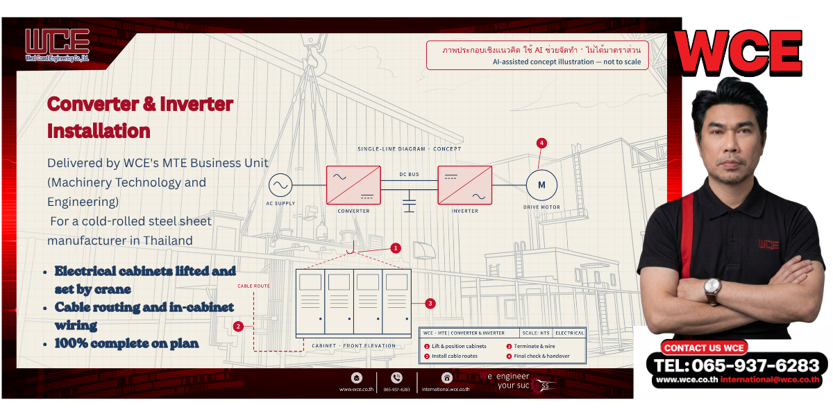
Many machines in a steel production line need precise motor speed control. A motor drive system with a converter and an inverter does this job. It also helps save energy. This article explains how an adjustable speed motor drive system works, the safety requirements, and the key points of installation. Finally, it presents a case study: a converter and inverter installation by WCE’s MTE business unit.
An adjustable speed drive controls the speed of motor-driven equipment. The most common type is the variable frequency drive. This solid-state controller adjusts the frequency and voltage supplied to an AC motor. As a result, the motor can run over a wide speed range [1].
In general, a motor drive system starts with a converter that turns AC supply into DC. Next, the DC bus carries this power to an inverter. Finally, the inverter turns it back into AC with adjustable frequency and voltage. In this way, the motor runs at the speed the process needs.
According to the US Department of Energy, input power for centrifugal fans and pumps varies with the cube of speed. Therefore, cutting speed by 20% cuts input power by roughly 50%. For constant torque loads such as conveyors, power varies linearly with speed [1]. In addition, adjustable speed drives allow precise process control and save energy in systems that do not run at full output all the time [3].
IEC 61800-5-1 sets safety requirements for adjustable speed drive systems. It covers electrical, thermal, fire, mechanical, and energy hazards for both low- and high-voltage systems [2]. For this reason, installers must follow the requirements for cabling, earthing and electrical clearances.
Converter and inverter cabinets are large, and their electronics are sensitive to shock. Therefore, the team must plan lifting points, lift with care, and set each cabinet in position. Only then does cabling and in-cabinet wiring begin.
First, MTE’s electrical service team lifted and set the cabinets by crane. Next, it installed the cable routes into the cabinets. Then the team terminated and wired the cables inside each cabinet. Finally, it checked the work and handed it over. As a result, the project finished on plan.
The cover image is a concept illustration. In the background, a perspective line drawing shows a cabinet being lifted beside the plant building. On the right, a single-line diagram traces power from the supply through the converter, DC bus, and inverter to the motor. A front view of the cabinets and the cable route sits below it, with the four work steps. All images were created with AI assistance, so no person or client can be identified.
Installing a motor drive system needs both safe lifting and careful electrical work. In addition, one team that handles both parts makes site coordination easier. For this reason, the work was delivered on plan.
WCE’s MTE (Machinery Technology and Engineering) business unit manufactures, repairs, and installs industrial machinery and equipment, including machine electrical systems.
Contact: +66 65-937-6283 | international@wce.co.th | www.wce.co.th
We engineer your success.

