Summary
A shredding shaft is the main shaft of a shredder, carrying high torque and repeated impact loads throughout operation. When this part has to be imported, local manufacturing reduces dependence on overseas suppliers. This article explains shredder shaft principles and how replacement parts are recreated, based on technical sources, then presents a job by MTE (Machinery Technology and Engineering) as a WCE case study.
1. What does a shredding shaft do?
A twin-shaft shredder uses two counter-rotating shafts, each fitted with several cutting tools that work like scissors to grip and cut the feed material. These machines run slowly with high torque; one manufacturer lists maximum speeds of about 11-18 rpm for its standard models, handling materials such as cables, small appliances, and scrap tires [1].
2. Key principles
2.1 A heavily loaded shaft
Machine design texts explain that shaft design must account for combined bending and torsional stresses, fatigue under repeated loading, stress concentrations at shoulders and keyways, and deflection that affects bearings and mounted components [2]. A shredder shaft carries these loads continuously, so it must be machined accurately to the dimensions and tolerances on the drawing.
2.2 Creating drawings from an existing part
When original drawings are not available, reverse engineering recovers information from an existing part to produce a new design. A study in MATEC Web of Conferences describes four stages: capturing the geometry of the original part, building a 3D model, simulating manufacturing by computer, and producing the part on CNC machine tools [3].
2.3 Why replace imported parts locally
A supply chain case study found that adding qualified alternative suppliers alongside the original equipment manufacturer (OEM) brings cost savings, shorter delivery times, and localization, especially when OEM parts become obsolete or hard to source [4].
3. Case study: shredding shaft manufacturing by MTE
– Scope: Design and manufacture of a new shredding shaft (position 2 of the machine) to replace an imported part
– Client: Steel recycling operator
– Duration: 20 April – 18 August 2026 (about 4 months)
– Progress: Plan 100% / Actual 100%
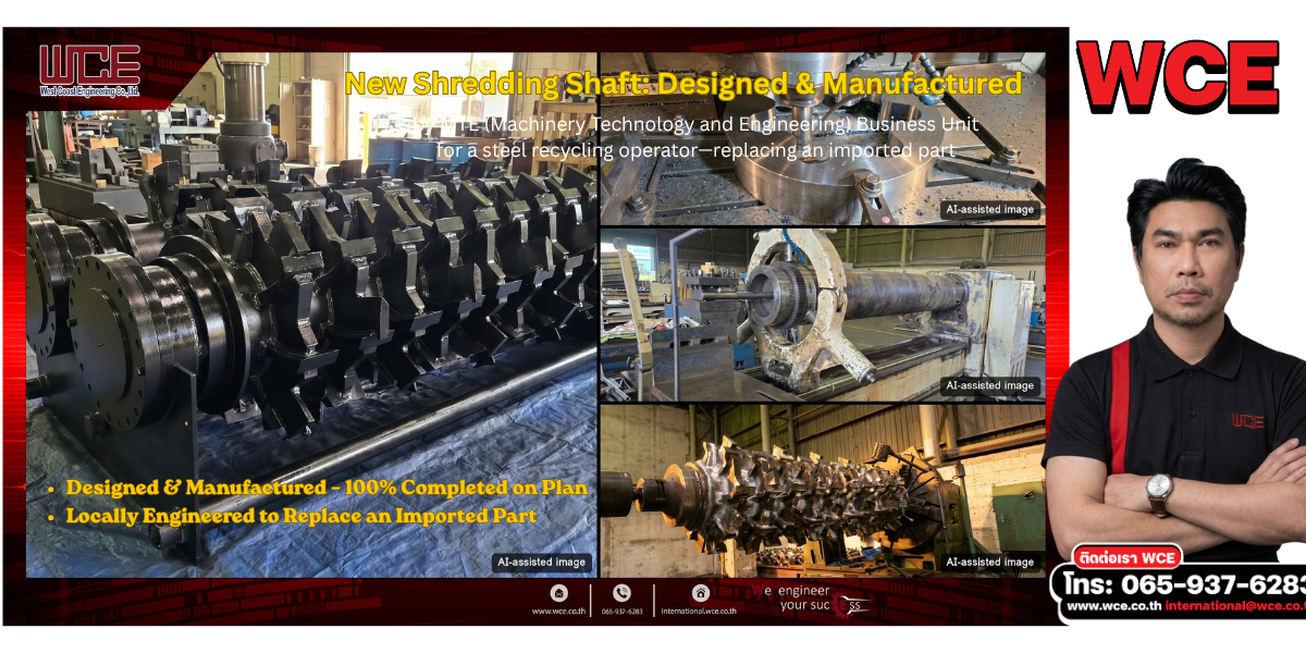
The cover image shows the work in stages. The large image on the left is the completed rotor assembly, while the small images on the right, from top to bottom, show milling of a disc-shaped component, turning of the shaft, and the rotor being turned on a lathe. All images were edited with AI so that no individuals or clients can be identified.
4. Observations
Large machine parts that must be imported can keep equipment idle longer than necessary. In this job, the MTE team handled both design and machining locally and completed the part fully on plan, offering one option for plants looking to reduce spare-parts risk.
5. WCE services
MTE (Machinery Technology and Engineering) provides design, manufacturing, and repair of machine components for industrial plants.
To discuss your project: +66 65-937-6283 | international@wce.co.th | www.wce.co.th
We engineer your success.
References (accessed 2 Oct 2026)
[1] BHS-Sonthofen GmbH (March 2023). Rotary Shear (VR)—Robust and versatile heavy-duty twin-shaft shredder (manufacturer product literature). https://www.bhs-sonthofen.de/CELUM/PIMCORE/BHS-Sonthofen/BU_Recyclingtechnik_REC/REC_Literatur_Anzeigen/Produktflyer_Rotorschere_VR_EN_2023_03_web_801000195.pdf
[2] Budynas, R. G. & Nisbett, J. K. (2019). Shigley’s Mechanical Engineering Design (11th ed.). McGraw-Hill. ISBN 978-0-07-339821-1 (chapter on shafts and shaft components)
[3] Stănăşel, I., Blaga, F., Buidoş, T. & Crăciun, D. (2018). Reverse engineering and the CAD-CAM approach for the manufacturing of spare parts. Case study. MATEC Web of Conferences, 184, 03004. https://doi.org/10.1051/matecconf/201818403004
[4] Al-Theeb, N. A. (2023). The impact of procuring reverse-engineered spare parts on the supply chain: A case study. Journal of Supply Chain Management, Logistics and Procurement, 5(4). https://hstalks.com/article/7761/

